In the context of BIM methodology, we most often hear the following terms.
Full integration, all platforms connected, one source of truth that all stakeholders use, lossless data transfer, the same standards of information, models designed directly on the construction site.
But what does that really mean? When can we conclude that we have reached the level where everything is connected and the data is up-to-date and properly selected?
Before we start this topic, it is worth looking at another issue at the beginning.
Table of Contents
What is information in a BIM project?
When we think about information in a BIM project, we probably have a 3D object with characteristic features before our eyes. Such as: geometry, shape, color. This object also has a name, texture and information about the material.
Suppose you are a road designer. You create a 3D model of the road that is enriched with various information. You share the created model with other stakeholders, as they need references when creating their models. However, you are still working on the model and the maturity status is changing all the time.
How can a domain expert determine that the objects and information to which his model relates are up-to-date?
And here comes another issue to discuss.
What opportunities do we have for cooperation in a BIM project?
Cooperation in the project BIM can be divided into two types:
- cooperation based on the exchange of files
- native (RVT, DWG, DGN)
- open (ifc, gml, LandXML)
- cooperation based on the exchange of objects / models BIM
In the first part of the article (1/2), we will discuss cooperation in a BIM project, which is based on the exchange of DWG / DGN files.
Collaboration in the project BIM based on the file-exchange
This way of collaborating is the most frequently chosen method when implementing BIM in a project at Level 1 and Level 2 (I guess 98% of projects worldwide).
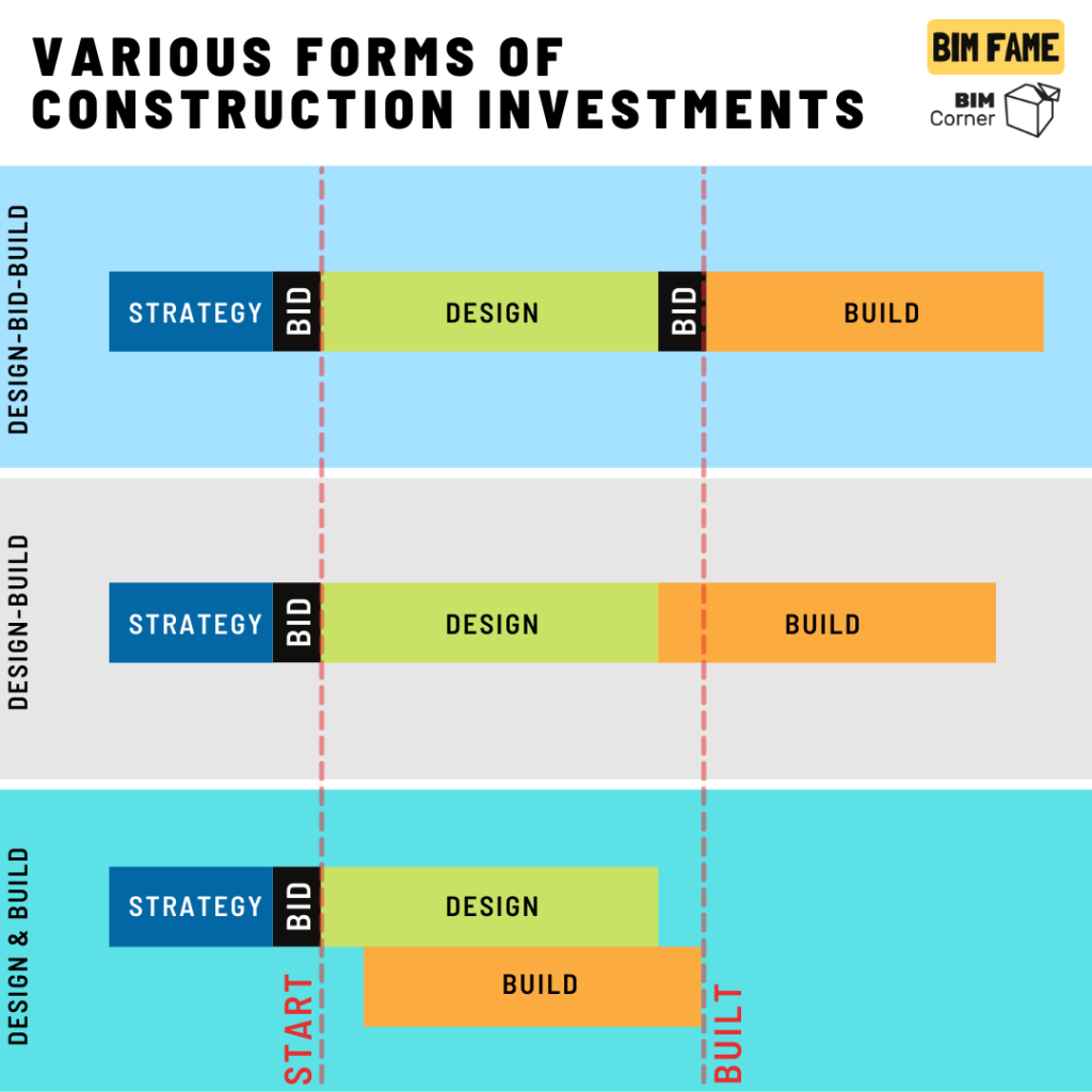
Design-Bid-Build is an example of a civil construction investment where this type of cooperation is used. In this type of investment, domain design takes place within one or more organizations. This factor affects the type of environment in which the files are kept during the lifetime of the project.
Design-Bid-Build
This form of contract is most often used in the case of small investments. It is distinguished by a sequential way of working. First, the contracting authority defines the strategy and creates the rules of the game, i.e. the tender. Then follows the design phase, the design documentation is created. This, in turn, is the basis for the next tender process. Finally, the selected contractor builds on the basis of design documentation.
Usually, the designer does not cooperate with the contractor during the investment. This creates a very high risk that the contractor may misinterpret the final design documentation. This sequence of things can lead to construction errors. These, in turn, may generate costs and delay the entire investment.
Thus, the key to a P-P-B investment is to define clear principles of operation already at the stage of the first contract, before the design stage. It is worth defining in such a contract what is to be the final product after the design phase and what the created documentation is to be used for.
Before designing
In addition to an investment strategy, it is very important to have a project strategy. I mean the designer’s strategy for carrying out the project. I will not go into the details of this issue in this article. In projects based on file exchange, well-defined rules and principles of cooperation are very important. For example, the structure of folders, determining how the file should be audited, and what the names of individual files are. A lot of rules, it is very easy to make a mistake due to the complexity of some processes.
Modeling of existing conditions
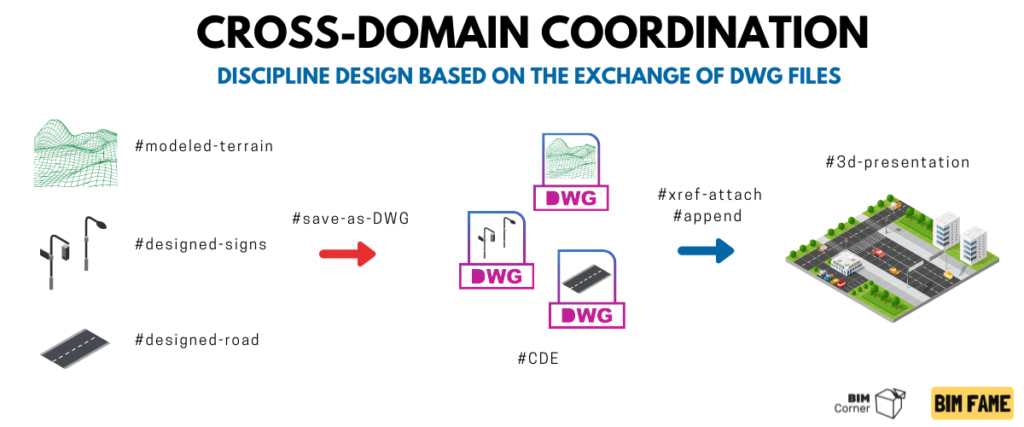
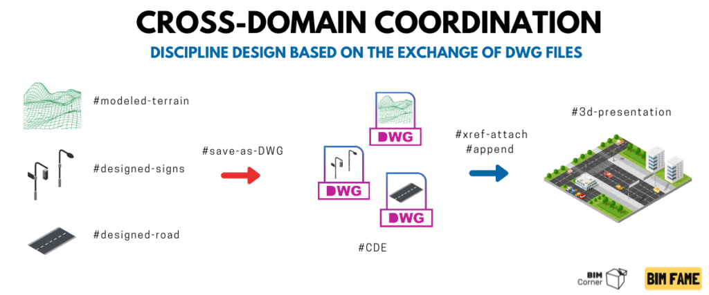
At the beginning of the design phase, documentation of the existing situation should be created. The existing situation is saved in different files, depending on the need. It’s best to save everything to the same format. The most frequently chosen format is DWG / DGN. Converted and saved files are the basis for the design of many domains. Such files can be a 2d map showing the existing communication routes, houses, fences, over- and underground installations, terrain model, etc. One file is one existing model.
Designing based on a DWG / DGN file
To design and generate project documentation, first of all, we need a tool that enables modeling of 3D solids. Currently, we can use any design tool on the market for these purposes. Let’s not forget that CAD drafting programs may also be sufficient here. I mean AutoCad and Microstation.
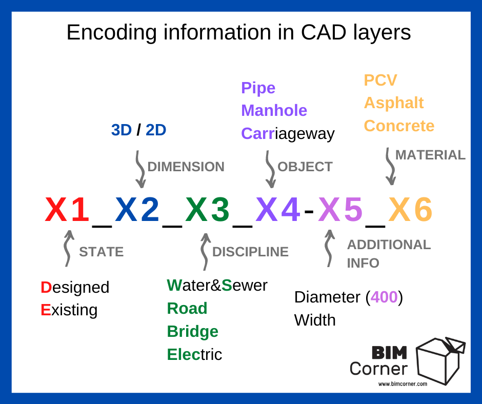
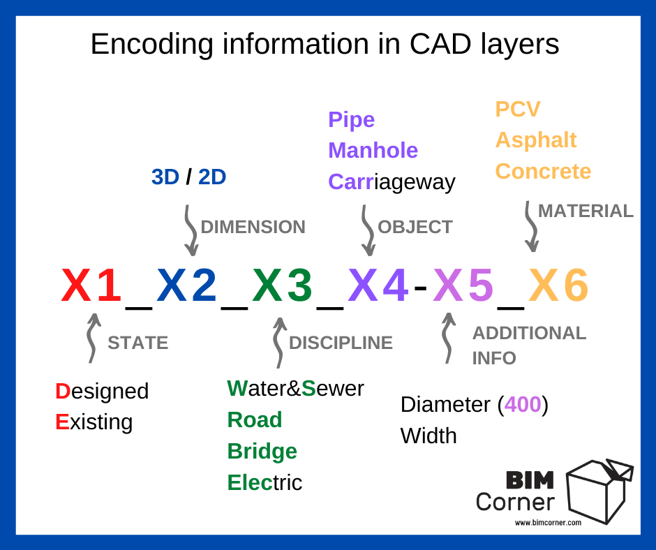
Then, when we create a 3D model that reflects a given discipline. We describe the elements that make it up with layers (I wrote about coding CAD layers here).
In the next step, we save this model as a DWG or DGN file (depending on which environment we operate in). One discipline may have several BIM models. However, one BIM model is one file. Information characterizing the BIM model can also be included in the file name.
Thus, each model in the form of a file has geometry (lines, point, curve, solid) and non-geometric information (in the file name, in the layer name). It is limited and not dynamic. One object, one geometry, one layer.
Cross-discipline collaboration
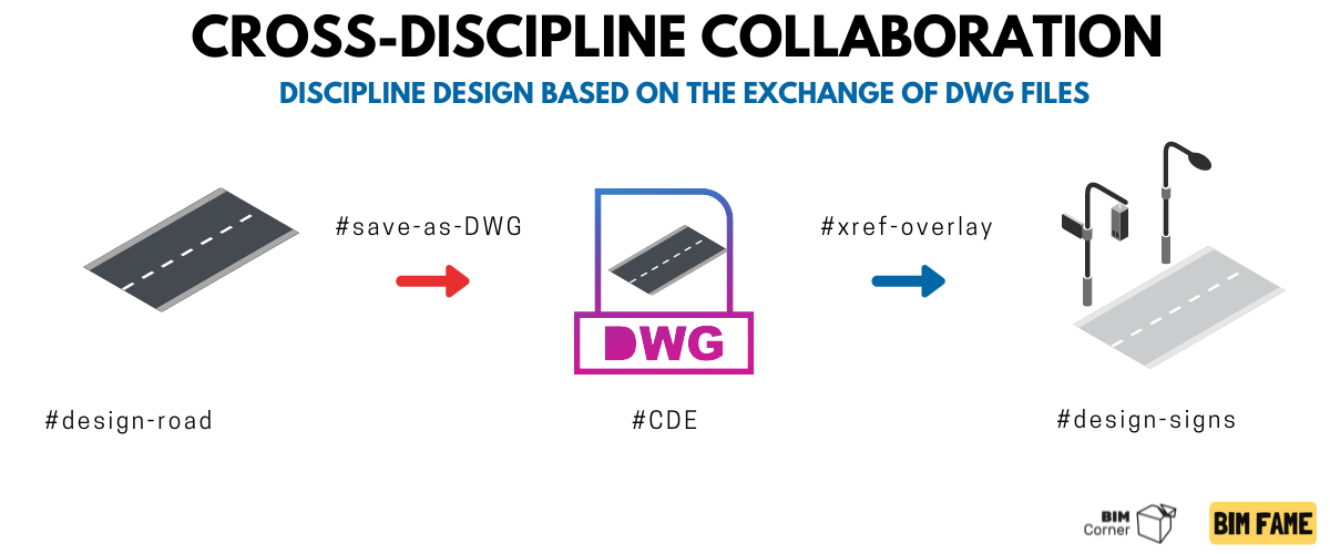
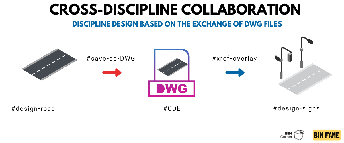
Road design starts with modeling a simple road corridor. Then the designer saves his road model to a file on the CDE platform, which is placed on the cloud server (The most popular CDE platforms are: Trimble Connect, Projectwise, Sharepoint). It may turn out that only domain specialists from one company take part in the project. Then, cooperation can take place within the DFS environment (which I already wrote about here).
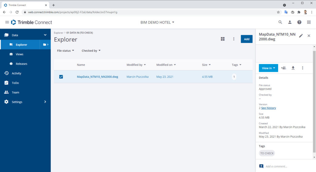
Depending on the environment in which we store our BIM documentation, we can assign different information to files such as status, date of change, file owner, etc.).
Then the discipline specialist, e.g. a sanitary designer, who wants to attach a road file to his project, has several options. The most popular is to connect the file directly from the storage location to the design program using the XREF / Nesting function (references in AutoCAD / Microstation), or similar. However, it happens that the designer prefers to work locally. Then he downloads the discipline file locally and binds CAD file to his model. In this way, changing the name of the file breaks the information about the model state and status.
It also happens that on small projects, when the project does not take place within one organization, the domain file is sent via ftp servers or e-mail messages.
It may turn out that industry files weigh more and more and have more and more objects as the project progresses and the level of detail increases. This can slow down your work and reduce efficiency. The CAD environment is not famous for its fluidity when we work with a large number of objects at the same time.
It is fair to conclude that this is not the most effective work process.
Cross-domain coordination
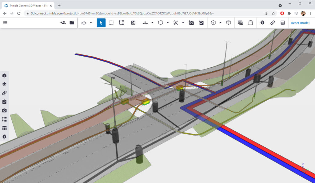
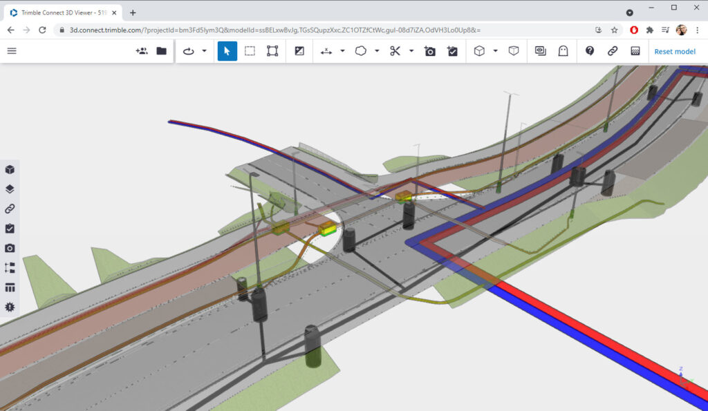
The federated file-based model is presented in the file viewer. The most popular applications are Trimble Connect and Navisworks. Trimble Connect has the advantage of being a browser application, with a mobile version and a Windows version. These two programs allow, among others, to display the content of CAD and IFC files. Trimble Connect also allows users to view the LandXML file, which is a very important format in road projects.
In file-based management, the multi-discipline model (federated model) is very rarely used other than in co-ordination meetings. Usually every 2 weeks. The use of the multi-discipline model during the design process is therefore negligible, as following the solutions contained therein may lead to serious errors (the multi-discipline model is very often out of date, as it is usually updated before coordination meetings). Moreover, coordination models are usually just only presentation models without information.
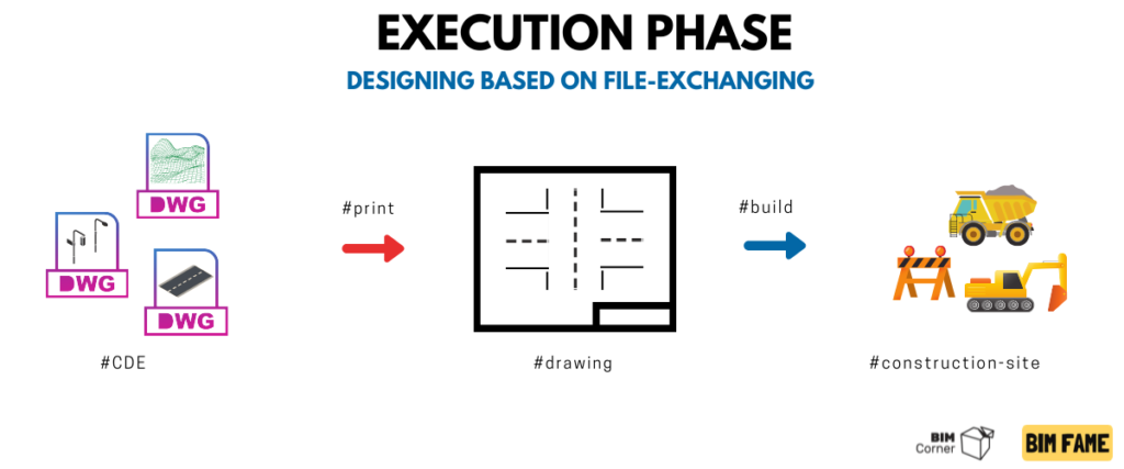
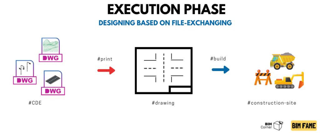
Execution phase and design documentation
Before the execution phase begins, a tender to select a contractor should be conducted based on the design documentation. I do not want to be a bad fortune teller, but I bet the thesis that more than half of all authorities in the world still use drawing documentation as the basis for the valuation of construction works.
So, based on the flat documentation, a tender is made. The contractor for construction works may receive file documentation, although usually in a non-editable PDF 3D, IFC, DWG format. These are closed files. After models are exported to these formats, they cannot be changed.
In order to adapt the model to the situation on the construction site, the contractor for his own use re-creates 3D models based on drawing documentation (here is the paradox of the whole situation). Based on a DWG file at best. Therefore, it is very important in this type of contracts (P-P-B) that the client’s strategy defines what is the end product of the design and what the product is to be used for during construction works.
Summary
So we have come to the end of the first part, in which I briefly discussed the principle of work in the form of a Design-Tender-Build contract based on DWG / DGN files. In the next part it will only be more interesting. I will introduce you to how we can work more efficiently and most importantly, how we can increase the use of a multi-discipline model during the design process









Thank for sharing, Marcin. It is a very helpful article. Looking forward the the next one.